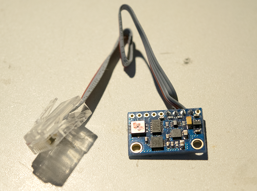
Having some experience with quadcopters, they all use something called an IMU – inertial measurement unit – which gives you the pitch, roll and yaw of the craft. These two values are generated by a gyroscope and accelerometer working together cancelling out each others possible errors. Additional measurements are normally available, a compass for direction and a barometer for altitude readings. With a GPS, the compass (magnometer) allows you to plot a course and have the vehicle follow waypoints; sounds like its worth a look.
An IMU board is now pretty cheap to get your hands on, in fact you can get a complete quadcopter ‘brain’ for $35 here, which contains an Atmel ATMEGA2560, with all of the above sensors ready to use. For my boards, a pre-made I2C board would be ideal which is exactly what I found; the GY-80.
Hardware

In order for this sensing unit to fit in with my existing network, it would need to have a RJ45 plug attaching the I2C lines and power. After crimping on a plug, I could plug the unit directly into my hub board and now it was just a matter of sorting out the software interface.
Software
Because these sensors are so widely used – especially with hobbyists who use the Arduino platform – there are already libraries available. With that said, most of them seem to be based off the same code which I originally couldn’t get working.
I decided to break down the process of retrieving data from the board into per-device blocks. First, the accelerometer then the magnometer. I wouldn’t be needing the pressure sensor for this project, and I’ve found them to be fairly inaccurate in previous projects. The gyroscope is handy for improving the readings from the accelerometer but I’ll leave that for a future improvement if its needed.
Accelerometer
The chip on the GY-80 is an ADXL345 – an extremely popular chip which can measure +-16g in 3 axis. The datasheet is pretty straight-forward to figure out the code that you need. I quickly tested the chip with libraries that are already out there and found that it was at least returning values.
Compass
The existing code out there to interface with the HMC5883L would not work with the Teensy 3. As the Teensy is a 32bit processor, there are differences in the way that variable types are handled. For example, `integers` now cover a wider range, so assumptions on their maximum limit will be incorrect. That appears to be the issue when using a Teensy, so a quick google around and I found this page where the inventor of the Teensy weighed in and gave a correction. Below is fully working code for a standard Arduino and the Teensy too:
[c]
#include <Wire.h>
#define COMPASS_ADDRESS 0x1E
float gauss_scale = 0.92; // Guass scaling
int16_t mag_x, mag_y, mag_z; // Compass values
void setup() {
Serial.begin(115200);
Serial.println("Starting");
Wire.begin();
setupCompass();
Serial.println("Compass setup complete");
}
void loop() {
readCompass();
Serial.print("X: ");
Serial.print(mag_x * gauss_scale);
Serial.print("\tY: ");
Serial.print(mag_y * gauss_scale);
Serial.print("\tZ: ");
Serial.println(mag_z * gauss_scale);
delay(100);
}
void setupCompass() {
// Sets the first (0x00) register to be 8 samples averaged, 15 hz, and normal measurement configuration
writeDevice(COMPASS_ADDRESS, 0x00, 0x70);
// Setup the scale to 1.3
writeDevice(COMPASS_ADDRESS, 0x01, 0x20);
// Set to continuous measurement mode
writeDevice(COMPASS_ADDRESS, 0x02, 0x00);
}
void readCompass() {
// We have to ask for a reading first, then get the result in one read. Order is definitely X then Z then Y
int16_t* buffer = readDevice(COMPASS_ADDRESS, 0x03, 6);
mag_x = ((int16_t)buffer[0] << 8) | buffer[1];
mag_z = ((int16_t)buffer[2] << 8) | buffer[3];
mag_y = ((int16_t)buffer[4] << 8) | buffer[5];
}
// Read a device after sending a data packet first
int16_t* readDevice (int I2CAddress, int address, int length) {
Wire.beginTransmission(I2CAddress);
Wire.write(address);
Wire.endTransmission();
return readDevice(I2CAddress, length);
}
// Read a device
int16_t* readDevice (int I2CAddress, int length) {
Wire.requestFrom(I2CAddress, length);
int16_t buffer[length];
if (Wire.available() == length) {
for (uint8_t i = 0; i < length; i++) {
buffer[i] = Wire.read();
}
}
return buffer;
}
// Write to a device
void writeDevice (int I2CAddress, int address, int data) {
Wire.beginTransmission(I2CAddress);
Wire.write(address);
Wire.write(data);
Wire.endTransmission();
}
[/c]
Results
After playing about with the GY-90, I found that the compass wouldn’t work if the unit was even slightly angled, and complicated tilt compensation would need to be applied. Not to be dissuaded so easily, I googled around and had a basic function which would factor in pitch and roll to give the correct bearing. The more I used the sensor, the less confident I was in its readings; the accelerometer never quite hit 1 on any of its axis, the bearing was slightly off and extremely sensitive to outside interferance. I was also using tilt-compensation code that I didn’t understand which made debugging a lot more difficult.

In the end, I decided to take the plunge and purchase a CMPS10 tilt-compensation compass from DFRobot. This unit is a little more expensive than the GY-90, but has a built-in processor which uses an accelerometer and magnetometer to give a tilt-compensated bearing. The unit also gives a pitch and roll reading, which were the only other 2 values I was looking for. All in all, this board is much closer to what I needed in my project; the only downsides are the slightly increased price and the shipping time from China (although DHL managed it in under 4 days).
Resources
ADXL345 datasheet – http://www.analog.com/static/imported-files/data_sheets/ADXL345.pdf
HMC5883L datasheet – http://www.adafruit.com/datasheets/HMC5883L_3-Axis_Digital_Compass_IC.pdf
GitHub – https://github.com/SorX14/Projects/tree/master/IMU