After working on my pond control project, I wanted to be able to increase the range of some M5Stack ATOM Lite modules. These modules are ESP32 based and come in a tiny form-factor.
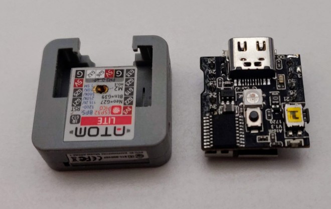
They open easy enough after removing the sticker on the back and then squeezing the clam-shell case. Only 3 parts make up the module – case halves and the PCB inside.
Case and the PCB side-by-side
Flipping over the PCB shows the 3D antenna connected to a capacitor-inductor network and the LNA pin on the ESP32-Pico chip.
3D antenna
The sheet-metal antenna is attached at 4 points – one top left, one top right (obscured) and the two bottom right in the foreground. With a little soldering and flux cleanup, the antenna is removed. I used a quick-clamp as a poor-mans PCB holder.
The left-hand pad is the LNA pin, and the right is a ground pad. The two upper pads are not connected to any trace I could find.
The idea is to get the antenna out the side of the case without interfering with the reset button, and also not coming out the bottom or rear (it would prevent the module from being used in the many modules – e.g. the PoE kit). I drilled a small hole in the case.
I cut back the end of a SMA pigtail connector, and tinned the ends.
I threaded the pigtail through the hole, and soldered the centre pin to the left pad, and the outer shield to the right ground pad.
Closing up the unit, I was ready to test
Before starting the internal antenna removal, I ran a simple sketch to list found AP’s. With the internal antenna, a maximum of 8 networks were discovered. With the external antenna, a maximum of 12 networks were found.
This isn’t the most scientific, but gives an idea of the improvement. I also listed the RSSI along with the AP name, and compared the two. The AP I picked was one that I had configured in the garden with 2 walls between.
The red – external – line clearly shows an improvement over the internal antenna.
The final step will be to add a small amount of epoxy to the antenna penetration in the side of the case for mechanical strength. Quick project done.
Our pond was slowly losing water over time, and I wanted to be able to track whether it was normal (i.e. evaporation) or if there was a leak in the pond liner. While doing this, I figured adding some temperature sensors would be handy to know when to restart feeding – fish shouldn’t be fed while the water is less than 10C.
FUN FACT 1: Fish go into low activity mode over winter and won’t eat. Anything you feed will just sink and rot; affecting water quality.
Water and electronics don’t mix, so deciding on a water level sensor took a while. Capacitive systems will eventually corrode, ultrasonic ranging would work but drift over time (small error compounds leading to poor consistency) and float switches don’t show continuous change. I picked an etape sensor which is a thin tube with known resistance which changes as the surround liquid presses on it. The sensor has a second resistive element which is not affected by liquid level, but allows you to compensate for temperature changes.
Using an m5stack Atom Lite MCU, I first tried the built-in ADC which has poor linearity and is bad range (0-1.8v from memory?), so I switched to an external ADC121C021 over I2C which was much better. Popped a couple of DS18B20 waterproof temp probes on and we’re good to go.
FUN FACT 2: ADC stands for analog to digital converter. Its actually a very complicated network of resistors and capacitors to turn a wobbly voltage to a digital reading.
All of this was installed into a waterproof junction box with power in, and the two temperature sensors out. Using custom firmware, I had a websocket-backed web GUI and also a Blynk app to use on my phone. The web GUI allows for depth calibration – connect the returned resistance (in ohms) to a depth (mm). The ADC module was conformal coated incase of water ingress.
Sponges for mechanical mounting pressure and a delightful touch of colour.
Installed with no cable management
Web GIU
Blynk app
Pond-ering forward
The next step was to automate the pond filter. The pond has a basic box filter which has a UV lamp in the top which the water must first flow over, then through various compartments containing different foams before being spat out the from two pipes. After a while the bottom of the filter gets full of fish poop and other biological goodness.
To clean the filter, it must first be drained with a tap (quick de-sludge) on the bottom, and then the filters washed. Before draining, the UV lamp should be turned off, then the pump (the water cools the UV lamp in normal operation). Using switches to do this is the boomer way, so we’ll automate it and waste countless hours invest time into speeding this up in the future.
FUN FACT 3: UV light causes algae to die and clump together giving you clear water. A more cheerful name would be the Algae Genocider
Filter diagram
Using another Atom Lite, I hooked up a 4 channel relay board, two additional relays and a previous energy monitoring PCB I designed a while ago.
Should have cleaned the flux and that isn’t a bodge wire, I don’t make mistakes
The energy monitor board needs 3.3v but the MCU sends 5v. As the serial lines are not isolated from mains, I used a ADUM1201 and a B0505S isolated DC-DC converter into a linear voltage regulator (5v -> 3.3v) and packed it on a prototype board (gray box with arrows and + – on it).
V1. Energy monitoring board is in the light gray junction box with the serial lines out the bottom.
Using the relays, the filter and the pump (both 240V) can be controlled. Using a 150W waterproof 12V power supply, the remaining pond things can be controlled – lights, ball valve and bilge pump.
Originally I used a 12V to USB power supply (the Atom Lite uses USB C to power it) but I had issues with the 12V PSU browning out with the bilge pump (it doesn’t have soft-start, appears as dead short to the PSU on start up) so I just used a mains USB PSU instead.
Before the ball valve, I intended to use a solenoid value to control the sludge line, but solenoid valves required a minimum pressure to work which this gravity-fed system couldn’t supply. I also intended to use a small 12V pump to move the water, but it didn’t self-prime and kept running dry. In the end, I picked up a motorised ball-valve unit which you control by either sending power to 1 of two wires.
A standard relay with its NO and NC contacts will be perfect here – NC for the green/blue wire and NO for red.
I used some clear pipe so you can see the fish turds flying through while draining.
Ball-valve and an embarrassment of mismatched brass fittings with a nice telfon-tape scarf.
Everything was hooked up, some coding and another app later, I can turn lights on and off, drain the pond and see if its empty.
Barely any visible wires – score!
Night-time debugging. Shows the old 12V pump and unused solenoid valve
Web GUI
App – combines depth/temp information
FINAL FOURTH FUNEST FACT: The pond level is mostly affected by evaporation. We don’t have a leak.
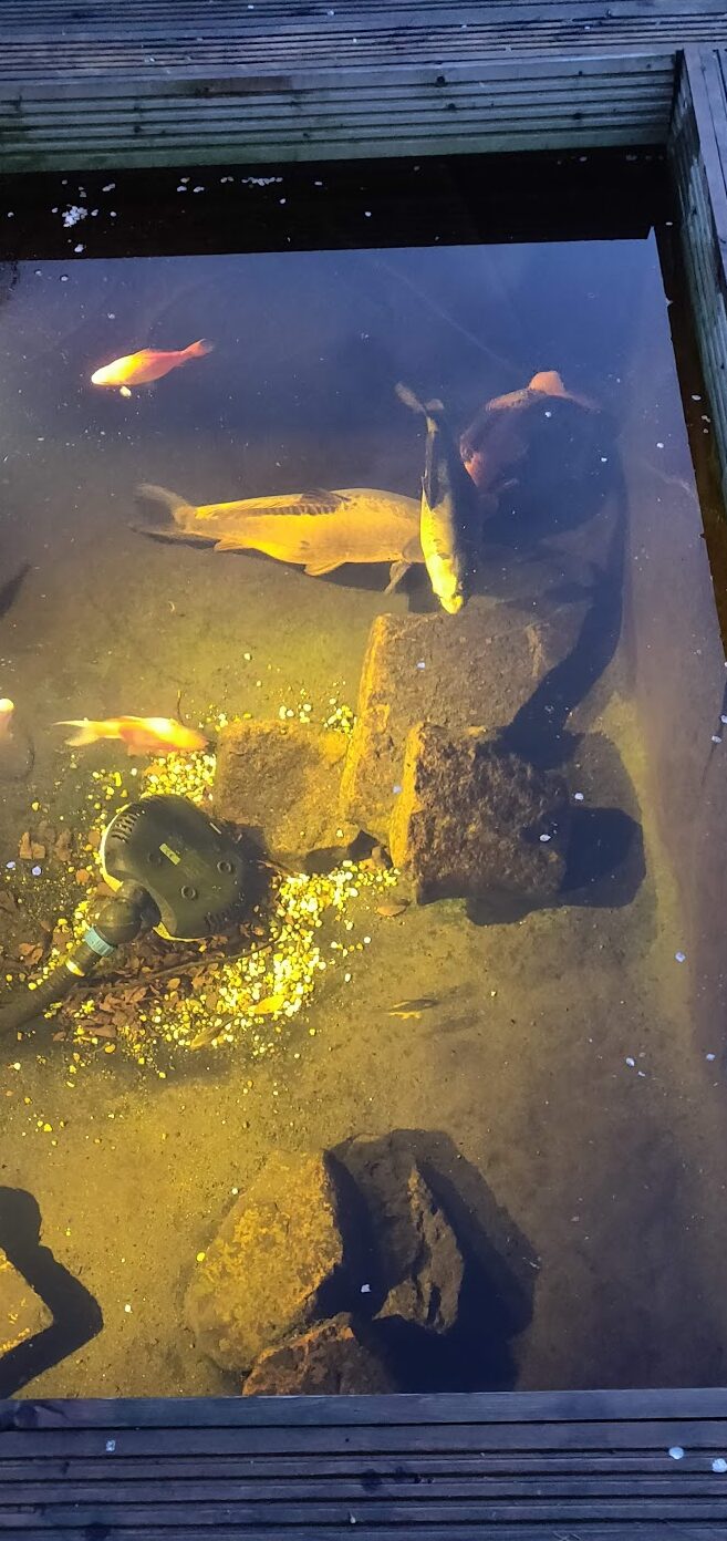
Pond with lights. I definitely didn’t just chuck the pump in