Cycling is my main form of transportation which often means I’m travelling at night, hoping other road users can see me as I ride along. I used cheap LED lights for a while, but the batteries either ran out too quickly, or their light output was sub-par. I looked around for a better more expensive set but ended up – foolishly – deciding I could do a much better job myself.
The first iteration was an Arduino Fio with a stripboard MOSFET driver board which lead to my discovery of OSH Park and – after a few months of experimentation and feature-creep – I ended up with a GPS RTC enabled board reporting its position and battery level back through a GPRS module. This board eventually suffered a catastrophic failure which I’m still unsure why it happened, but I was left without lights which was my biggest concern.
Design
All of these boards were massively over complicated for the job they had to accomplish; flash LEDs. I decided it was time to drop all of the nonsense and create a super simple (comparatively) board which would have the capability to connect to another decide later on. I fired up Eagle and set to work.
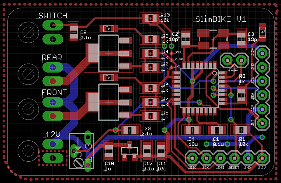
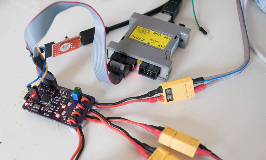
The end result was a 50 x 30mm board with 2 STN4NF03L MOSFETs, an Atmel ATMEGA328P and all of the accompanying passives. The 12V input is supplied by a 3S LiPo which has an absolute maximum voltage of 12.6V and an absolute minimum of 9V; this voltage is measured via voltage divider implemented with a multi-turn potentiometer. The input voltage is lowered to 3.3V by a MCP1703 linear regulator which has a very low quiescent current; needed for long battery life when the microprocessor is sleeping.
Each MOSFET has a low-power red LED on each of the outputs allowing for easier debugging. The input switch contacts have a pull-up resistor, as well as a capacitor which does a good job of removing the need for software de-bouncing. A debug LED sits in the top right corner, next to the crystal and the serial output pins. On the right edge, there is a pin connector with 3.3V, GND, 12V, INT and I2C pins which will be useful if I decide to connect a second board which would have more intelligence. The bottom right edge has a custom layout ICP header allowing me to program the bootloader-less chip.
The switch, 12V inputs and front/rear outputs all have a strain-relief hole which I can snake the cables through to give a stronger connection.
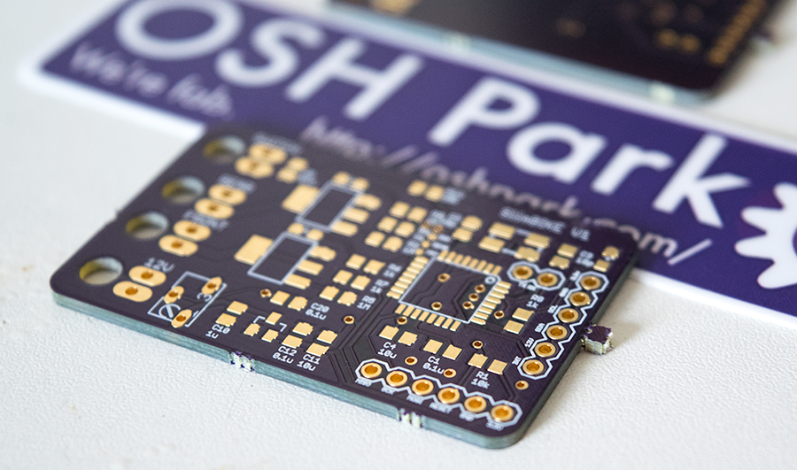
I sent this design off to OSH Park for fabrication, and within a few weeks, I had the PCBs.
Soldering
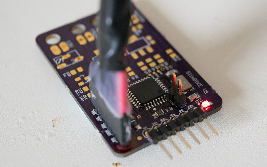
I’ve made a few PCB’s now, and soon I had the bare essentials to program the ‘328 bootloader. After messing about with drivers for my Olimex AVRISP MKII programmer (incidentally the Windows 8 drivers can be found here) I uploaded the Uno bootloader and had the debug LED flashing away.
I carried on soldering away, until the entire board was complete and I was ready to start work on the software.
Code
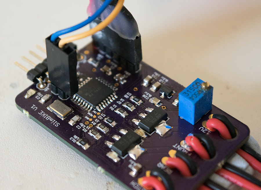
The first thing to calibrate was the pot as it could connect the 12V input rail directly to a delicate processor pin. To prevent damage, I powered the board with 5V that the chip can easily handle, and – using a calibration script – I soon had the divider set up correctly.
Now that the hardware was finished and calibrated, I set up a list of things I wanted to be able to do with the software:
- Have two light operation modes
- Half power – battery saving while still being visible
- Full power – full illumination for especially dark roads/paths
- The ability to check the voltage
- A deep sleep mode to save battery power while not in use
After reading an amendment to the cycle laws, you can use flashing LED’s providing they’re between 1 – 4 Hz. Using the MsTimer2 library, I set an interrupt function to run every 150ms, so the rear lights will flash just faster than 3 times a second.
The sleep mode was provided by the LowPower library and is as easy as LowPower.powerDown(SLEEP_FOREVER, ADC_OFF, BOD_OFF);
Using interrupts on the switch would wake the chip from sleep, and then start flashing in half power mode. If the switch was pressed again, the lights would go into full power mode. One more press and everything goes back to sleep. If you hold the switch down for 2 seconds, you’ll enter the voltage read out mode.
The voltage read out mode will get the current voltage, then using long and short front LED flashes, output the voltage.
[c]
int voltage = getVoltage();
int whole = voltage / 100;
int fraction = voltage % 100;
Serial.print(whole);
Serial.print(".");
Serial.println(fraction);
voltBlink(whole);
fadeFront();
voltBlink(fraction);
[/c]
First the whole number is output, then the fraction or decimal points. If we had a voltage of 12.21, then whole would be 12 and fraction would be 21. The front LED’s use a long flash for 5 and a short flash for 1, so to output 12, you would have 2 long flashes, and 2 short flashes. The 21 would be 4 long flashes and 1 short flash. This gives me a way to determine whether I need to recharge the battery.
Resources
GitHub – https://github.com/SorX14/Projects/tree/master/SlimBIKE