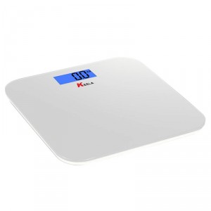
For a while I’ve wanted to connect some scales to my home network to track weight day by day automatically. Its great having scales, but unless you can remember or write down the previous readings, its pretty useless if you’re looking to track performance. So I set about figuring out a way of getting an accurate reading from a set of cheap bathroom scales with an Arduino.
Background
I bought 3 different kinds of scales, but they all had one thing in common – strain gauges. It seems as though the simplest and cheapest way of getting the weight of an object, is to use strain gauges which, for bathroom scales, 4 seem to be the magic number. All of the scales I found had 4 feet on the bottom which connected to an LCD display. Each of these feet is a little strain gauge which is a very simple measuring device. The one I ended up using was sourced from here.
The gauge is a piece of metal that is allowed to bend slightly, and in doing so, causes the resistance to change. If you have resistance change, you can measure it and voila – you’ve got a method of measuring weight. Obviously there is more to it than this, but for our purposes, this explanation covers it.
![By Rhdv (Own work) [GFDL (http://www.gnu.org/copyleft/fdl.html) or CC-BY-SA-3.0-2.5-2.0-1.0 (http://creativecommons.org/licenses/by-sa/3.0)], via Wikimedia Commons](/wp-content/uploads/2014/10/Wheatstonebridge.svg_.png)
This all sounds great and we can just plug the Wheatstone bridge straight into an analog to digital input on the Arduino and diet away. Well, strain gauges only change resistance by a tiny amount, so the Wheatstone bridge voltage is equally minuscule. As the Arduino only has a 10 bit ADC, it has a minimum resolution of 4.9 mV with a 5 V reference. You can set the reference to be an internal 1.1 V, but you would still only have steps of 0.1 mV; the bridge’s output is less than 0.01 mV for my scale.
Measuring
The Arduino has a 10 bit ADC, but there are much better and more accurate ADC chips available. I chose this one – a MCP3424 chip – from JeeLabs which had a nice breakout (designed for his JeeNodes), 4 channels and 18 bit accuracy. Even more useful was a programmable gain of upto 8 meaning an incoming signal is first multiplied by 8 before being measured. For tiny signals that we’re measuring, that’s perfect.

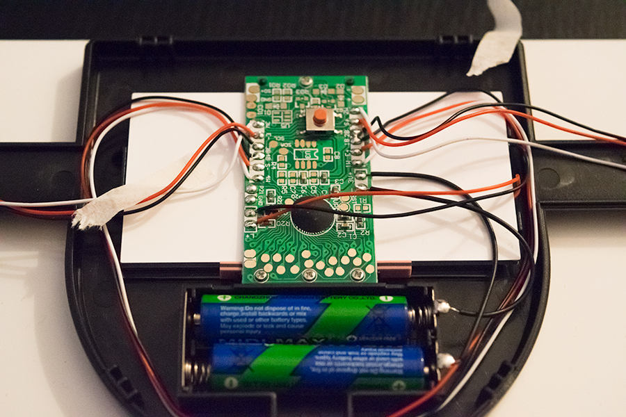
Thankfully, the PCB I was working with had silkscreen labels showing which wires are which. There should be 4 important ones, S+, S-, E+ and E-. These stand for Signal and Excite, with signal being the output, and excite being the input voltage. The other connections are just the strain gauges being connected together through the PCB.
I noticed that there were several unpopulated sections on the PCB, and there are labelled SDA and SCL test points. I figured that this same PCB is also used in higher end models which have memory capability containing an I2C EEPROM. It might be possible to get readings via these pads, but I don’t own an oscilloscope to investigate with.
Measuring the excite pins, I got a voltage of 3v, which was the same as the input voltage delivered from the two AAA’s. The output voltage from the excite pins was around 0.01 mV with no load. This is perfect, as I wanted to use a 3.3 V microcontroller so I could use an XRF radio module.

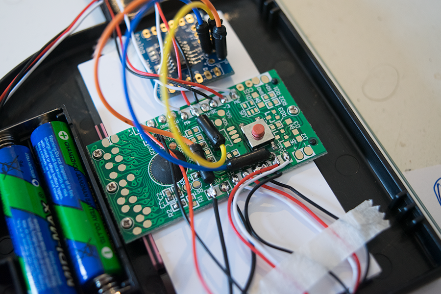
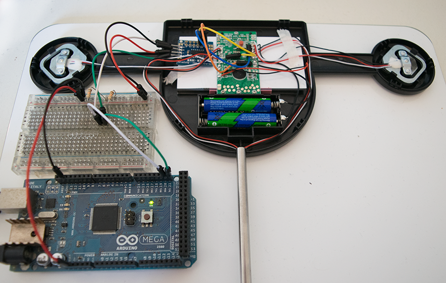
I first prototyped the circuit and connected it up to an Arduino Mega connecting the S+ pin to 1+ on the MCP3424, the S- pin to 1- and then connected the grounds. The bridge would still be powered by the scales circuitry so its important to have a common ground. Even with the gain set to 8x, the highest reading with my full weight of 75 kg was only ~ 1000 which works out to be about 10 per kg. I’m not 100% sure what units I’m reading the result in, but that doesn’t matter, as I’m only interested in its relationship to a known weight.

Finishing
Once my circuit was proved working, I extended the wires out of the battery compartment and now I could measure my weight as usual with the scale’s display still working as before, but also viewing the readings through the serial monitor.
I couldn’t figure out how the scales determined whether they should turn on, so I’m just going to use the LCD backlight wires (the backlight turns on when the scales are stepped on) and link it to an interrupt to wake a sleeping Arduino.
The ADC is a little over spec’d for what I need, so I’ll design a PCB that uses a MCP3422 which has the same specifications as the MCP3424, but only 2 channels. I’ll continue my project once the PCB has arrived.
Hi, Nice one!
I’m looking to hack some digital scales and connect up to an Arduino so your post came up via google.
Are you able to share which scales you based the article on and where you purchased from (I’m also in UK) ?
Thanks!
Oops, follow up! Found your link to the Ebay scales you used. They’ve sold out though, will look for another vendor.
I did buy a second set of scales from another eBay seller which I’ll hopefully have a look at this weekend. All of these cheap scales will work the same way, they just might not have the pins nicely labelled on the silkscreen.
My custom PCB arrived also, so I’ll share the details later.
Cool!
This morning I purchased a cheapo Lidl (silvercrest) bathroom scale for the princely sum of £7.99.
I’ve opened the back up and had a look at the PCB, it does have S+, S-, E+, E- terminal marked up, which is great!
If you don’t mind I might be asking you about the wiring of this thing….. (I’m a programmer not an electronics bod 😉 )
Hi, I’m looking to give this project a shot but have a few questions:
1. What model of scale did you use? The eBay link is broken for me.
2. Does this scale have rest mode? I’m looking to measure a constant weight, so would like to disable sleep mode.
3. What other materials or tools are required for this project?
Thank you!
Pretty much any model of scales will do the trick; they change too quickly to give an exact model number. They all work the same way.
Most scales have a rest mode, where if they don’t detect a change in weight they’ll go to sleep. Can’t think of a way to get around this to constantly measure weight, unless you bypass the scale circuitry altogether.
This might be more useful: https://www.sparkfun.com/products/13230 which is an amplifier allowing you to get the raw readings from the scale which would allow constant, continuous measurements.
Best of luck with your project.
Is there a way to calibrate a weight scale to show weight in Moon weight calculations?
Would be helpful if can shed some light on it.
Thanks in Advance!
Hi Steve,
I am looking at recalibrating the scale to show weight of a person on moon.
Can you give me any tip about this, please?
Thanks in advance!
Easy enough, calibrate it to Earth weights, and then multiply by 0.165 (Moon weight is 16.5% of the Earth). Simple 🙂
Hi Steve!
Nice page, I’m also working on a similar projet, to get the weight of my beehives in realtime (every 30s), as well as the temperature, and humidity.
I’ve used the same process as you did, found the S+, S-, E+, E- on the scale PCB, and connected wires to it.
But from there, I’m trying to use a HX711 ADC to connect the sensors to my arduino board. I’m having trouble to get results, so I’m thinking that it might be related to the fact that the scale board already amplifies the signal ..?
Should I disconnect completely the scale PCB and only use the sensors on my HX711 ? (I wanted to keep both together, so I could check the results for my testing phase)
Cheers !
Hi again!
Well, the original PCB from the scale was interfereing the HX711. I decided to remove all the scale’s electronic, so I just kept the sensors that I plugged directly to my HX711, and that works fine !
I lost the scale’s digital display, but I just needed that for testing purpose, so it’s not a big deal.
Awesome, glad it worked out for you
what do you do with the E+ and E-