I’ve tried my hand – literally – at quadcopters, submarines, and RC buggies, and now its time to make a tank. Hmmm, I guess more of a tracked box but we’ll call it a tank.
While searching for information on the subject, I ran across a website describing how he had made the treads out of bike chain and acrylic, the motors were ripped from cordless drills, and the chassis was essentially adult Meccano. All of this looks to be within the realm of possibility, and has the potential for being massively over-engineered – the best way to engineer.
Motors
When designing something from scratch, I find it useful to get the dimensions of the things that cannot change or be changed. For instance, if we found that the motors would be 20cm long, that’s an unchanging value; the chassis has to be able to hold a motor 20cm long. With this in mind, we set about picking the best motor for the job. The general consensus seems to be that cordless screwdriver/drill motors are the best bet because they have a hard-wearing planetary gearbox with gear ratios that make sense when you’re looking for plenty of torque.
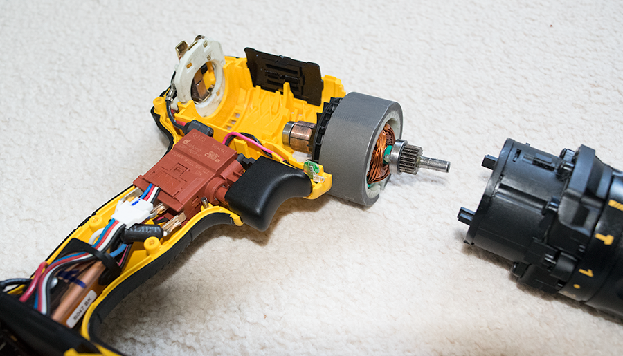
This was enough to get the credit card out, and a quick visit to Ebay, and a DeWalt DCD785 N 18V XR COMPACT 2 (~£40 body only) was dispatched. This drill was extremely well made, and had a nice feeling of quality; unfortunately – once open – it was clear that it wouldn’t be usable in the project. The motor itself was open-body and not a sealed unit, so it wasn’t possible to just take the motor and gearbox out and mount it elsewhere. Sigh… back to the drawing board.
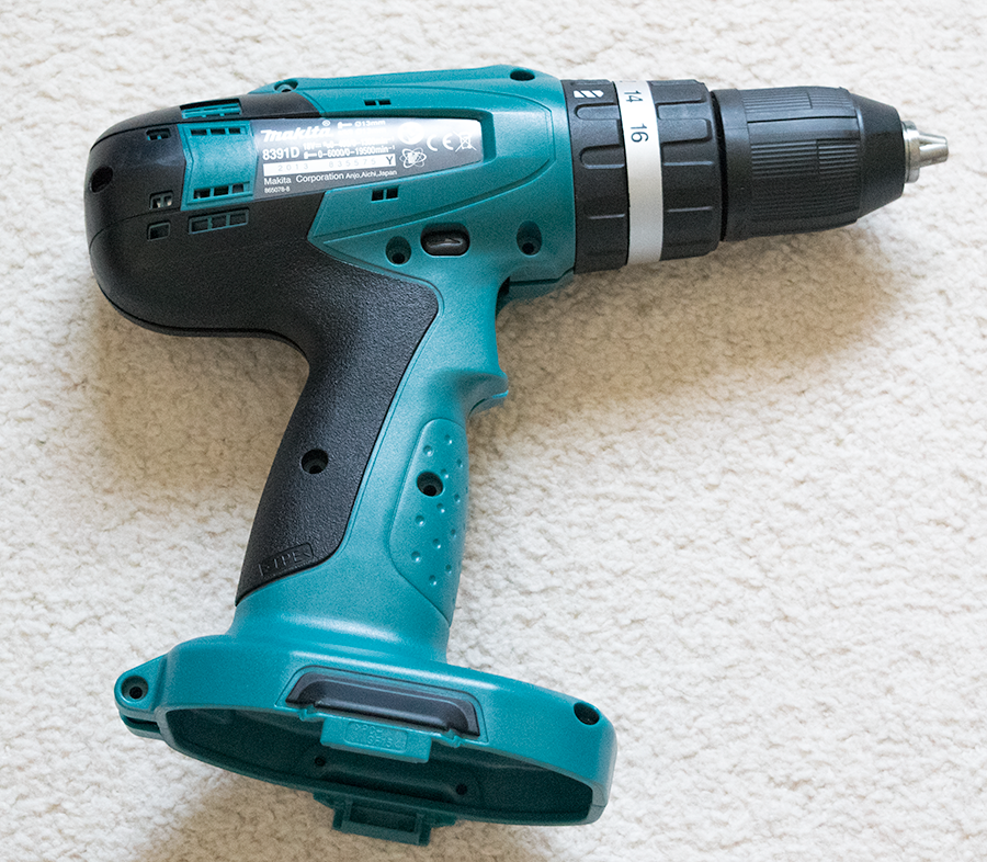
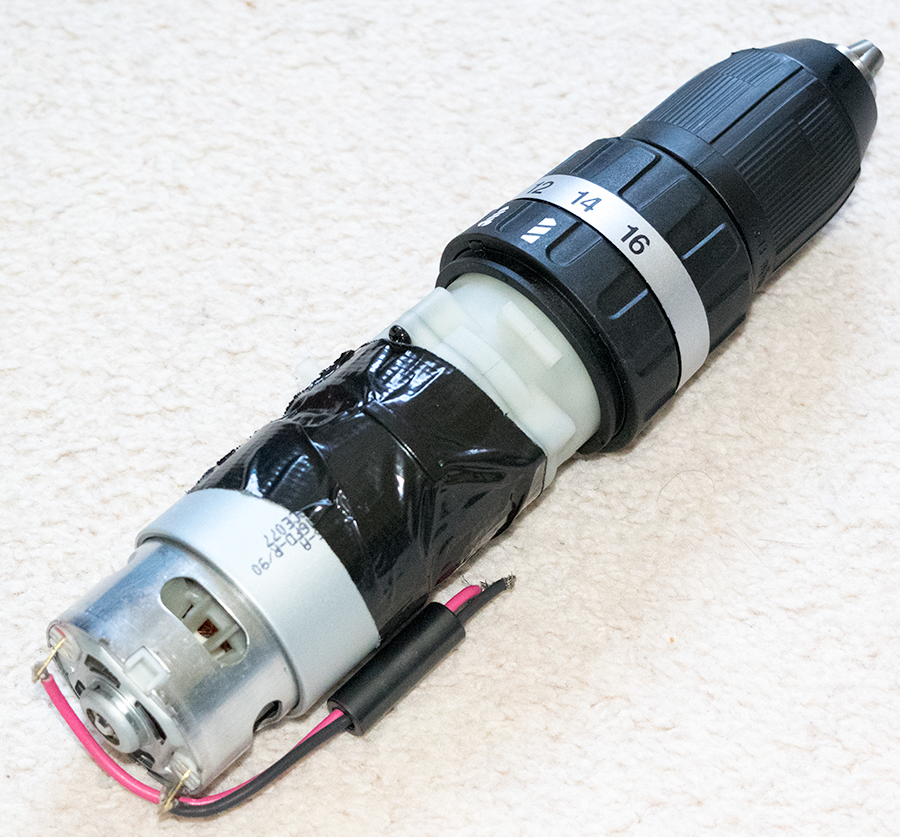
After being burnt last time, we checked the documentation of the next drill we were looking to get – a Makita 8391D 18V – and it showed that the motor and gearbox were separate sealed entities; perfect. It was clear that this setup would be powerful enough to drive the tank, but the length of each assembly was concerning; to have both motors mounted at the rear would need a ~50cm wide chassis. Before rushing ahead with this plan, I took a look to see what else was out there.
[column-group]
[column]
[/column]
[column]
[/column]
[/column-group]
Going brushless
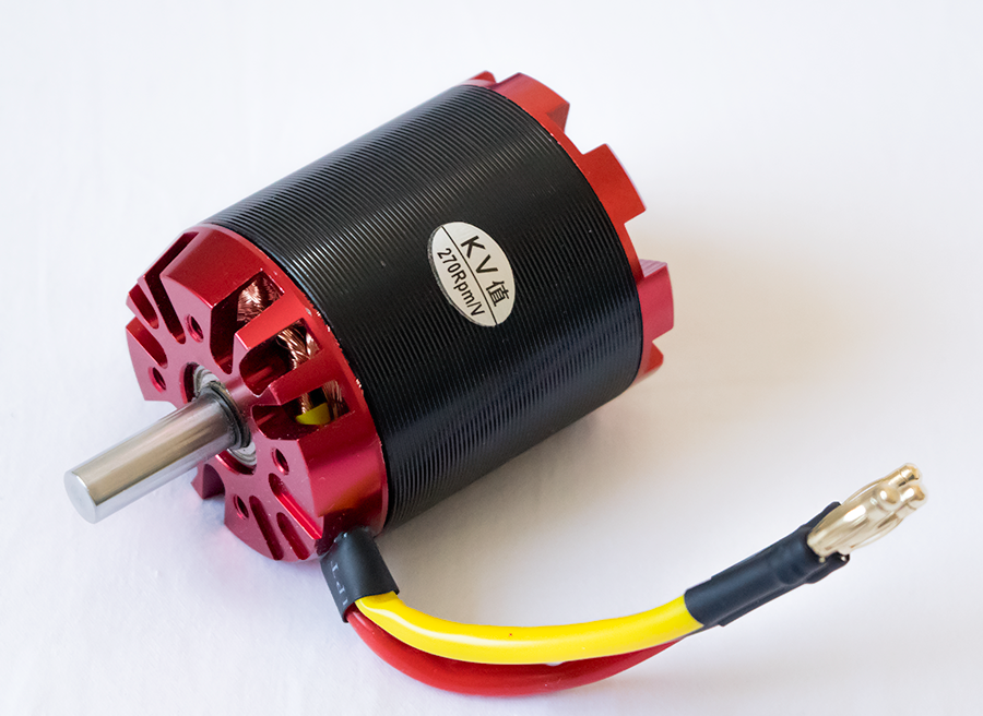
I started to have a look at brushless motors as I’d used them previously on my quadcopter. They are more powerful, more efficient and all-round better than brushed motors, but require a more complicated control method. Thankfully there are plenty of electronic speed controllers (ESC’s) on the market which will do all the hard work for you. After picking out a motor – N5065/08-KV270 Outrunner – all I needed to do was find an ESC capable of driving the thing.
I wanted to use LiPo batteries as they have a ridiculously high capacity and also a high discharge rate meaning you can draw a lot of amps if you need it. As I was ordering from HobbyKing I figured I would get the order in quick as they tend to be a little slow. My 5S 18.5v nominal battery packs appeared the next week. Now I have my specs that the ESC has to fill; 100A max draw, 5S battery compatibility and reverse drive. What a pain in the ass it was to find one…
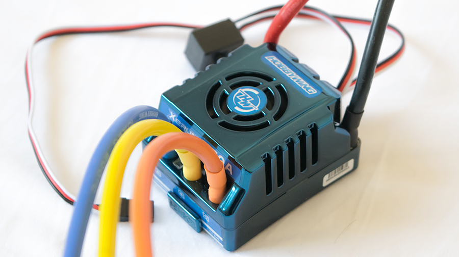
In the end I went for a Hobbywing XERUN-150A-SD for the low, low price of £85. It would appear that there are plenty of ESC’s out there but they are either:
- Too low amperage
- Only one direction – lacks reverse
- Too low voltage; cannot handle more than 3S batteries
I was loath to spend so much, especially as I’ll be needing 2 of them… Anyway, I could now run the brushless motor which was capable of consuming up to 1750W which seems fairly ridiculous. ESC’s are controlled via PWM (the same as servos) as they’re designed to be used with standard RC receivers. Fortunately the Arduino Servo class can produce the correct PWM signals easily. Reading through the documentation for the ESC, sending a servo value of between 0 and 89 will reverse the motor, and 91 to 180 will drive it forward. 90 becomes ‘neutral’, and you can extend this neutral band to be wider if needed.
Now I have motors with standard mounting points, ESC’s with enough power and features to drive the motors, batteries capable of supplying sufficient current, and a bunch of torn apart drills.