With the mechanics somewhat decided on, the control circuitry was the next on the list. After ‘mastering’ radio control, temperature sensing and internet connectivity, I was pretty well versed with the Arduino ecosphere, and felt pretty comfortable making my own PCBs with the help of OSHPark.
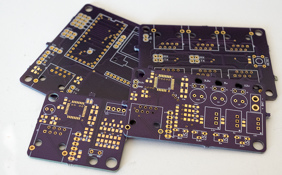
I felt the tank needed multiple separate boards, not only to compartmentalize functionality but to work around the maximum board size in the free version of Eagle I was using to design the circuit boards. After much deliberation, I settled on 4 boards; control, connectivity, LED, and power.
Fundamentals
I decided that I would connect the modules together using ethernet cable as its cheap and I’ve got piles of them, but using a custom pinout. The modules would communicate with I2C or serial, and would all be connected to a central reset button. By using a modular approach it meant that I could add in modules at any point and extend the functionality. This was especially important as there was the possibility of mounting different turrets. The pinout I decided on was:
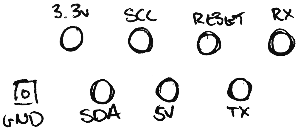
Which was my best attempt at wrapping like pairs together (GND + 3.3V, SDA + SCL, 5V + RESET, TX + RX). The actual pinout doesn’t matter to the cable as long as standard ethernet cables are used, and not the cross-over variety.
The intelligence of each module would be provided by an Atmel ATMega328P-AU running @ 16Mhz which would be programmed via a custom ICP header rather than using serial uploading.
Controller
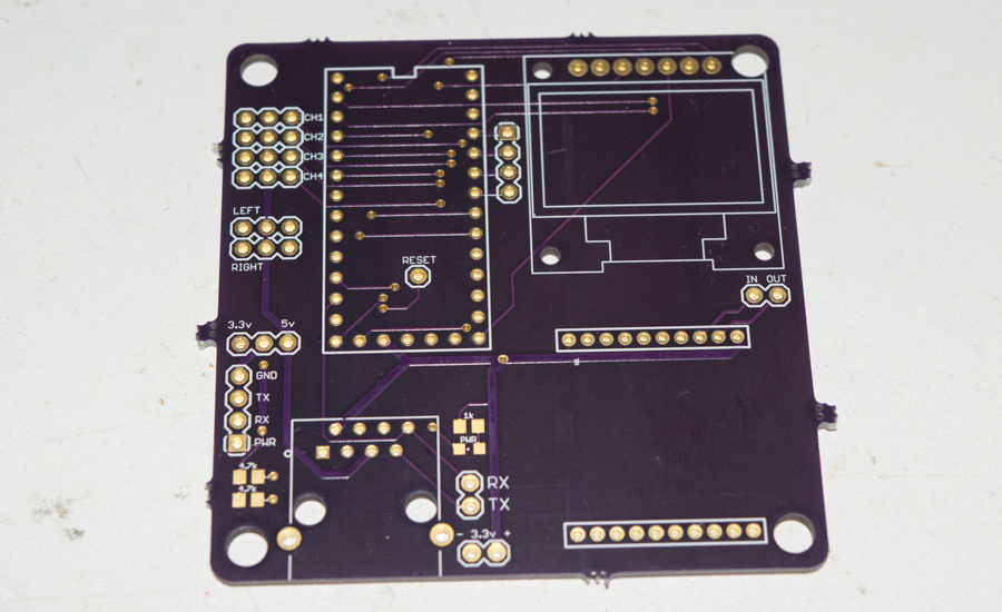
While preparing to order another project, I noticed that a new version of the Kickstarted Teensy 3 was available – the Teensy 3.1. I originally backed the Teensy 3 but never really used it to its full potential. I figured for $17 delivered its a no-brainer. Its an Arduino-compatible board with 64kb of RAM, 256kb flash and 72 Mhz core frequency, which makes it perfect for displaying graphics where a large frame buffer is required, or for tasks that are computationally intensive. Maybe a tad overkill, but I hate running out of RAM and having to go back through and optimise everything.
Considering its power, I figured it would make sense for there to be some kind of graphical output to make debugging easier. I found the perfect screen, a SSD1306 OLED 128×64 SPI unit. It takes either 3.3 or 5V, and is controllable over SPI. Thanks to an awesome library written by Adafruit, drawing and writing to the screen is extremely straightforward; even adding your own images (mental note, in LCD Assistant, the settings are default orientation, little endian and 8 pixels/byte. Make sure that the width is a multiple of 8 otherwise it’ll be cropped).
I needed to also connect a GPS – either a 3.3 or 5V version, an RC receiver module, the 2 ‘servo’ ESC outputs, and a radio. I decided on an ARF module from Ciseco (incidentally, worst name for a company; you can’t google a misspelling for them as it’ll just turn up Cisco) which will work with my existing XRF network for testing, and then be capable of extreme range in the field. The ARF is an XRF with an amplifier stage so it can transmit much further (claimed to be 10’s of kilometers). One downside is that when transmitting – which will be all the time – it uses 330mA; a third of my power budget.
I tested a method of capturing RC signals from a standard receiver which would act as a backup control method should the ARF fail, or if I can’t get it working correctly.
Resources
Schematic and Eagle files – https://github.com/SorX14/Tank/tree/master/PCB/Controller%20board
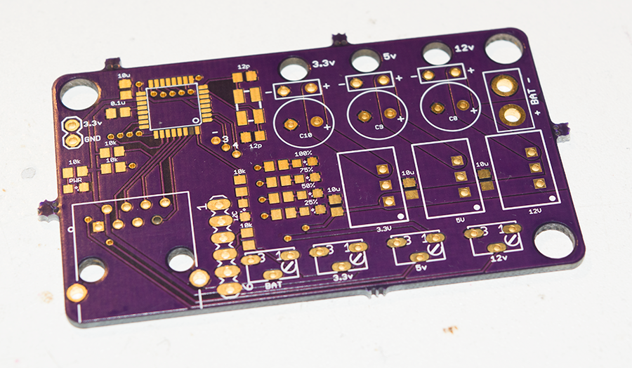
Power
I had a 5S battery, which has a usable voltage range of 17V to 21V which a fairly large swing. From this I need to have a few regulated rails:
- 12V – For LED strips, or solenoids
- 5V – For any add-on boards that need it, e.g. GPS modules
- 3.3V – All of the microcontrollers and logic.
I’ve used a few method of regulating voltage depending on the application and figured that switching regulators would give me a few extra seconds battery life, and would allow me to draw significant current without overheating anything. While looking for components, I found some new Traco Power modules which have the same pinout and similar footprint to standard 78XX regulators, but have fully-potted switch-mode internals – TSR-1. These regulators promise better accuracy, lower standby current and a 1A maximum output. They also can accept much higher voltages (up to 36V) which I needed for the 21V max when the battery is freshly charged. Running 21V down to 3.3V would be a significant amount of heat with a linear device. The only downside of these modules is that they need a slightly higher voltage than the output and they’re much more expensive (~£5 each) than the standard linear type.
I wanted to be able to monitor the state of each voltage rail to make sure everything is within tolerance, so I added in some potentiometers which would act as voltage dividers for each rail plus VBAT. An added consequence of knowing the voltage of everything was that I could put a little fuel gauge on the PCB itself using 4 LEDs connected to PWM pins.
Resources
Schematic and Eagle files – https://github.com/SorX14/Tank/tree/master/PCB/Power%20board
TSR-1 datasheet – http://www.tracopower.com/fileadmin/medien/dokumente/pdf/datasheets/tsr1.pdf
Connector
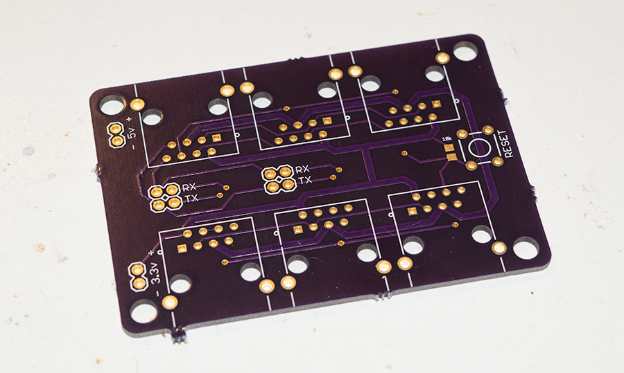
The connector board was the easiest of the lot, just a much of RJ45 connectors all wired together. The only extras were:
- 3.3V and 5V test points
- A reset button with pullup resistor
- Serial jumper points
The reset button will allow me to restart all of the connected boards which I’ve always ignored doing in previous projects and ended up having to unplug things to cycle the power. With so many boards it made sense to have one button to restart everything. The Teensy can self-reset with a software call, meaning it can detect the standard reset signal and action it itself, or send a reset signal to the other devices.
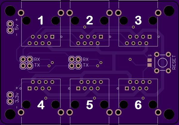
Each of the connected boards have their serial pins connected to this board. Serial isn’t a protocol that can directly handle multiple conversations at once so only the bottom two RJ45 connectors can have their serial pins connected to the controller board. The controller board would connect to port 1, and then either ports 4 or 5 can be configured to communicate with jumpers.
Resources
Schematic and Eagle files – https://github.com/SorX14/Tank/tree/master/PCB/Connector%20board
LED boards
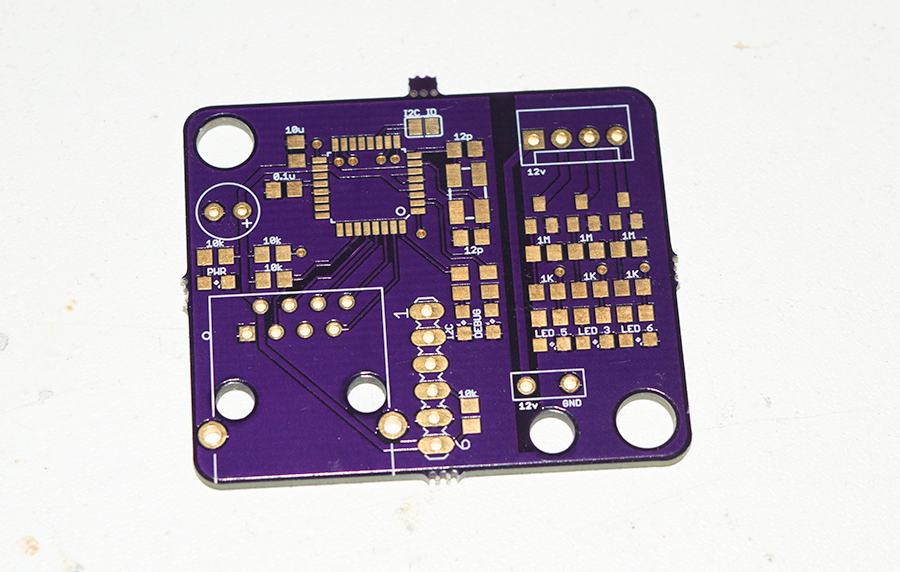
These are probably meant to be in a different class altogether – they’re more like accessory boards, things that aren’t needed for operation but provide additional functionality. I ended up ballsing up the silkscreen on the back of the boards which I haven’t fixed in the repo.
These boards will provide the ability to control common-anode LED strips with 20v and up to 1.3A. In actuality, I’ll be using them to control 12V LED strips that will be well below the 1.3A ceiling, especially as the 12V rail has a limit of 1A anyway.
I added in RGB LED’s for each channel to allow testing prior to finding the LED strip that I’ll be using. Quick note, make sure you get LED’s that have the same average light output as otherwise you’ll end up like myself and have dim red, bright green and eye-piercing blue.
Resources
Schematic and Eagle files – https://github.com/SorX14/Tank/tree/master/PCB/LED%20board