For my tank project I needed a failsafe should my serial radio link crap out on me, and as I had a standard RC transmitter lying around, it seemed natural to use it. After doing a bit of reading and prototyping, I managed to come up with a fast, non-blocking method of capturing the RC signals and converting them into a usable value.
Theory
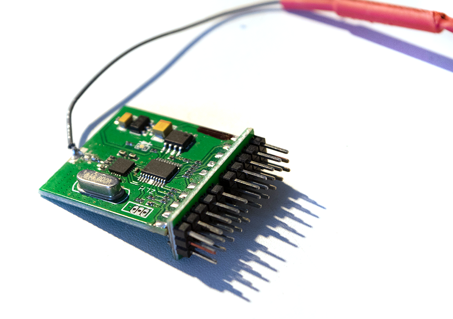
My setup consisted of a Turnigy 9X transmitter which is capable of channels of PPM data; it can also do PCM but I believe the implementation is pretty crappy/incomplete. No matter, we’re not interested in how the data gets from the transmitter to receiver, just the servo data that comes out of the available 8 channels.
PWM (pulse width modulation) is the method that servos use to decide their angle. It was chosen as its pretty good at being sent over radio links, and its also very easy to decode with light-weight electronics which makes it perfect for RC airplanes and models. The basic idea of servo control is a frame lasts around 20ms, and at the start of the frame the signal goes high. It stays high for X amount of time, before returning to low until the next frame. The amount of time the signal spends high determines the servo position. According to Wikipedia, the average pulse length is 1.5ms which would be the neutral point on a servo, or 90° for a 0 – 180° servo.
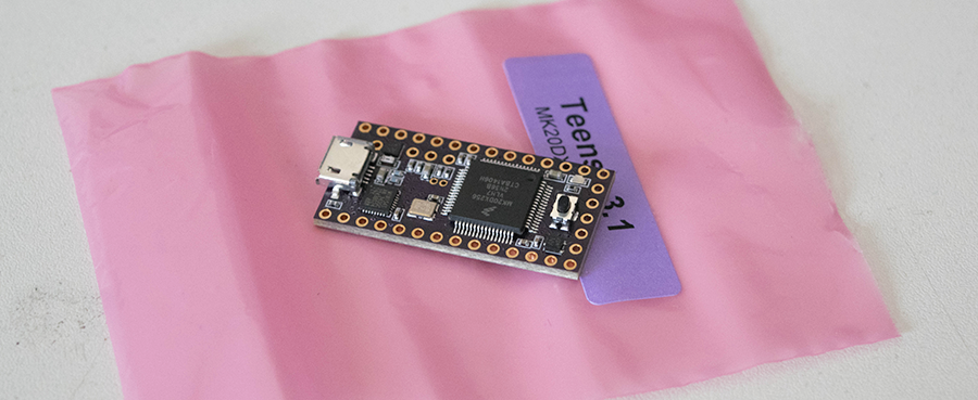
To get the Teensy 3.1 to digest the signal, we’ll be using the hardware interrupts which are available on every digital pin. The process is pretty straight forward, and the people over at RCArduino have gone into detail about the subject; I’ve just modified the code for usage on the Teensy.
Code
All we need to do is monitor for changes to the input pin, and when the pin is high, start a timer. When the pin changes and returns low, stop the timer and output the difference. Thats it.
[c]
// Define which pin we’re using to accept the signal
#define RCPIN 1
// We have to declare as volatile as this will be modified
// by the interrupt routine, and read outside of it
volatile uint16_t channel;
uint16_t channel_start;
void setup() {
Serial.begin(115200);
Serial.println("Starting…");
// Mark the pin as an INPUT
pinMode(RCPIN, INPUT);
// Attach an interrupt handler to be called whenever
// the pin changes from LOW to HIGH or vice versa
attachInterrupt(RCPIN, RCchannel, CHANGE);
}
void loop() {
// Output the channel value
Serial.print("RC channel:\t");
Serial.println(channel);
delay(50);
}
void RCchannel() {
// If the pin is HIGH, start a timer
if (digitalRead(RCPIN) == HIGH) {
channel_start = micros();
} else {
// The pin is now LOW so output the difference
// between when the timer was started and now
channel = (uint16_t) (micros() – channel_start);
}
}
[/c]
This same process can be expanded out to allow multiple channels to be monitored; for my purposes, 4 channels will be monitored. As we’re using interrupts and a nice, quick routine, we probably won’t even notice that the counting process is going on, and we’ll be able to do other things while the channels are being watched.